Are oscilloscope diagnostics still relevant?
An oscilloscope or a scanner for diagnostics should only be used where it is most rational and will give a more accurate result. They can be used both separately and together, and sometimes as an addition to the main device.
Let’s consider their use in diagnosing a 2002 Mitsubishi Outlander DOHC not MIVEC 2.0l. All the necessary maintenance procedures were carried out on the car: replacing the fuel filter, washing the nozzles, spark plugs, oxides – dirt is shorter, the engine was washed with flushing oil, all oils and fluids were changed.
A diagnostician can have a large number of devices. Take a close look at what you have and consider whether they are all being used effectively. Take, for example, an oscilloscope.
Why, when I use an oscilloscope, I do not record a single script? Because there is no need to automatically analyze the data. A competent diagnostician can do this on his own, considering and analyzing data in relation to revolutions. For example, by making corrections to the operation data of the ignition, fuel, air, VVT systems and seeing how the system reacts.
And determining the location of the fault is another problem. There are other devices and methods for this. As for the mechanical part, an oscillogram from the vacuum sensor was given. To carry out detailing, it is necessary to turn on the channel with a sync pulse. And use the sweep line of the free channel as a horizontal guide …
Or, if necessary, install a pressure sensor in the cylinder, and without igniting the mixture, take an oscillogram. This was done earlier, before A. Shulgin’s scripts appeared. This tool was very much in demand, during a period when the scanner was more used to read fault codes, and displayed parameters like the MMC above.
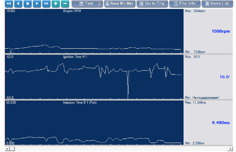
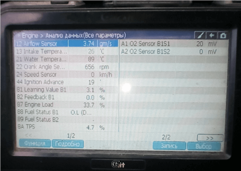
Above are the parameters recorded on the scanner and their graphical display. You can move the graph, select points with a marker. All values in the comparison point will be displayed. Only to combine them, as on the chart in the script, will not work. It turns out that the oscilloscope has outlived its own? No. The oscilloscope remains the same. And the device performs its functions clearly. But a diagnostician who uses additional sensors for analysis must himself connect the data output by the oscilloscope and the data of some non-electrical process output by the sensor.

Above are two control pulses per coil, the normal normal control pulses. Such distortion in amplitude is normal.
Below are oscillograms from a single-channel simplest oscilloscope, but not burdened with an upgrade of controls and updates. This is MMC Lanser.
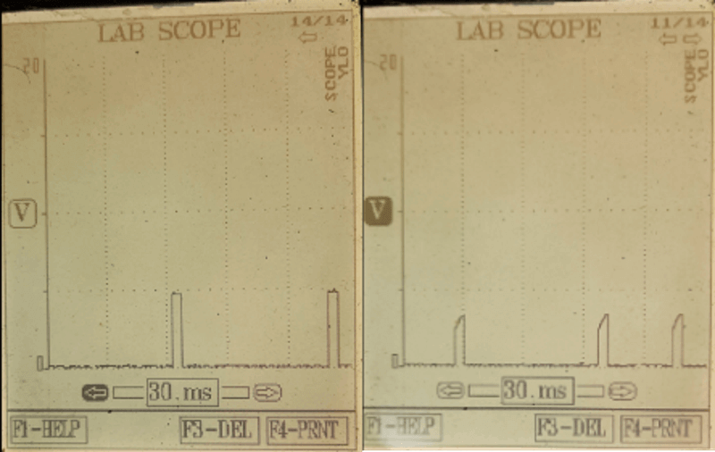
The oscillogram on the left is faulty, on the right is working. The most informative signal is not the one that is more even, but with distortion – it is closer to the real one. You also need to remember to make sure that the coil is being checked (at least by the number of pins), so as not to look for a malfunction where it does not exist.
Consider now the next part of the waveform. On it, the number 2 indicates what is between the fixed markers A and B.

Below we see what is located from marker A towards marker B.

We see that on the original section (to marker A), everything was fine. To see what happened, we scale it so that this section of the waveform with markers fits on the screen:

In the image we see the following. 1 – to marker A; 2 – between markers A and B; 3 – after marker B. After marker B, the correct pulses again indicate good coils. Most likely, the problem is located in the area from the block to the coils. Probably sting. If it were possible to deploy and amplify the interference signal, then one could assume that this is.
It makes no sense to take an oscillogram of the current through a power element (key). It is clear that it is triggered by interference. How does this happen? As in reality, most likely the result of poor contact with ground in the output stage of the driver or the junction itself in the output transistor. The pulses received in section 2 (between markers A and B) are unsystematic, reminiscent of spark interference. Wiring cannot be ruled out either, it can also have a contact where it should not be. And it can arise and disappear, obeying the “law of vibration of the engine.”
In this case, the oscilloscope helped identify the location of the fault, eliminate suspicions of coils, and set the right direction for further troubleshooting.
